
This is the third major update to the CDP/LLDP packet sniffer (First, Second). The main processor is now the ESP32 microprocessor. Of the available packages, I’ve chosen the TTGO T-Display. I would like to give a shout-out to Colin for his assistance, and for testing what has been (at times) some cringe worthy code. There has been some pretty poor work-arounds to resolve issues, and then (hopefully) cleaned them up later. If you notice any remaining please let me know.
You can see below that the wiring is far simpler than the previous versions. This is thanks to the T-Displays extra built in options.

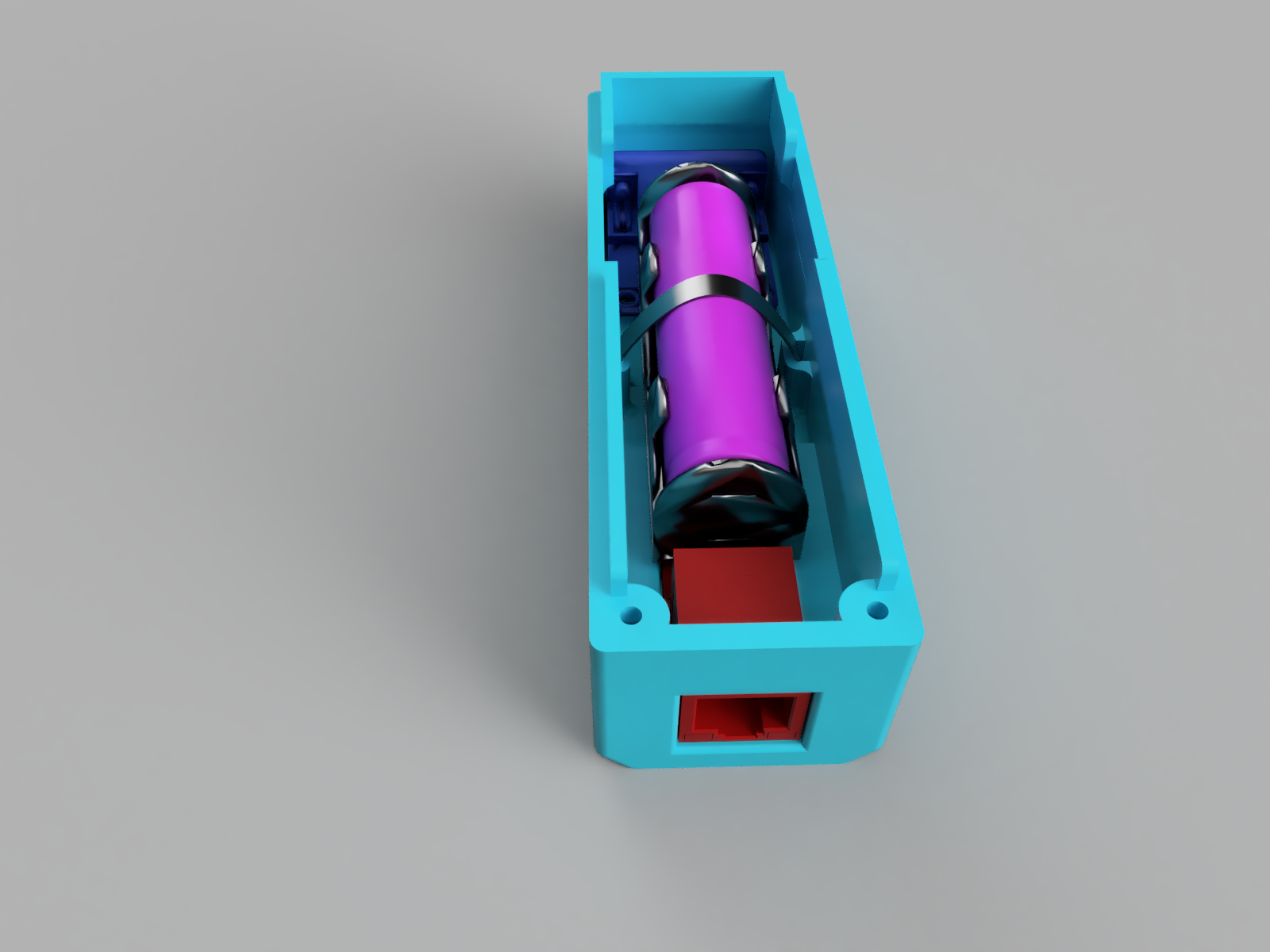
The major changes in the T-Display: built in TFT, charging circuit, and Bluetooth. The red mosfet is used to distribute power to peripheral devices. The reason for the mosfet is to turn off peripherals while in Deep Sleep mode. Without it, the battery (a single 18650) is drained in less than 24 hrs because the ENC and RS232 convertor never power down. With the mosfet the Deep Sleep mode uses <1mA – I cant say exactly how much as my multi-meter doesn’t swap between mA and uA automatically. Now a button on the T-Display can be used as a soft off option (Deep Sleep).
The T-Display has far more memory than the old Arduino’s, so more options can be written into it. It still performs CDP and LLDP packet capture, and it does it more reliably. This is thanks to the addition of PID checking, it now disregards DTP, VTP, and a few other packets that share the same broadcast MAC address.
// This PID is for CDP only and will filter out VTP, DTP, etc..
String PID = print_mac(EthBuffer, 20, 2);
if (PID != "20:00") {
return (0);
}
DHCP has also been tweaked by making sure the millis stays above 0 and makes sure the link is still up. If DHCP fails, you can initiate another request by “long pressing” the left button.
(Credit: @Colin)
while (dhcpState != DHCP_STATE_BOUND && uint16_t(millis()) - start < 20000 && ENC28J60::isLinkUp()&& uint16_t(millis()) - start > 0) {
		if (isLinkUp()) DhcpStateMachine(packetReceive());
    }
    updateBroadcastAddress();
    delaycnt = 0;
    return dhcpState == DHCP_STATE_BOUND ;
It has been changed to ask for all 256 DHCP options. For those times the VLAN is correct but DHCP is way out. The common options have been setup, and it wouldn’t be that difficult to expand it to include more.
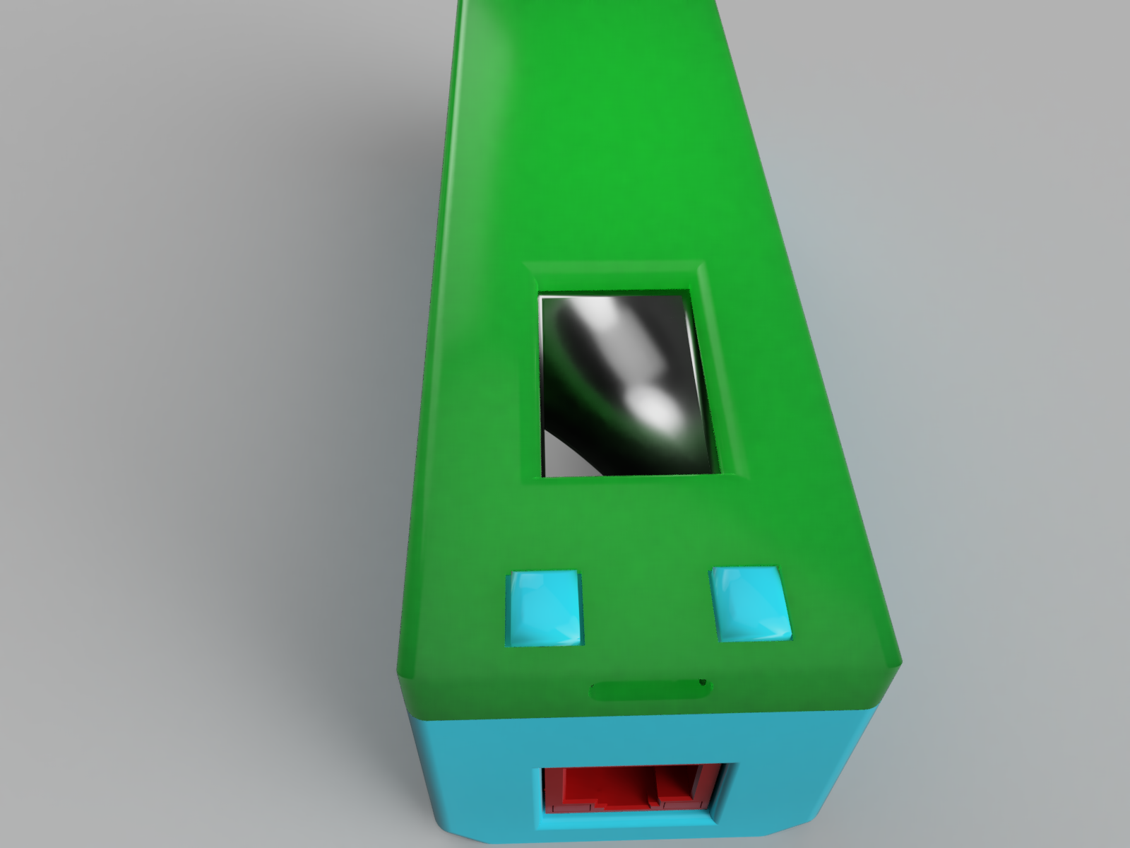
Enclosure
STL files: CDP ESP BASE, CDP ESP LID, CDP Buttons
The enclosure has the following design features:
- The screen, buttons and USB-C measurements were taken from this model: https://www.thingiverse.com/thing:4501444 Credit: https://www.thingiverse.com/pjmi/designs Licence: https://creativecommons.org/licenses/by-nc-sa/4.0/
- It’s slightly smaller and far more pocket friendly than previous models.
- Micro switches are no longer needed as each of the buttons on the T-Display have multiple functions.
- The battery is held in with a zip-tie, which also helps to keep the hot-glued mosfet in place. This does make changing battery challenging but it’s fine for now. It seems like a dirty fix, but I like it.
- During construction all pin headers and the screw terminals on the mosfet PCB are removed and wires are soldered directly to the PCB’s to save on space.
- In the base below red object is the ENC, then the mosfet, dark blue is the RS323 to TTL convertor, and purple is the battery – zip tied down using the mounting slots in the sides of the base.
- The mount used to anchor the battery was on the bottom middle, but it was found to be far too easy to snap off.
- You’ll also notice that only one edge has screws to hold the base to the lid. The tolerances between the other 3 edges is tight enough to hold the lid firmly in place.
- The gap along the top lip in the base is to allow the RS323 converter to drop through it and be mounted on the rear wall. This was a tough decision as the long walls could be bowed out to to accommodate the extra width, and the long lips toward the front become more susceptible to snapping off since they don’t connect with the rear section.
- Some lite filing may be required along the outside of the lips in the base to make sure it fits firmly but still allows the lid to be removed for maintenance.

Code Changes
There has been massive changes to the main code and some minor changes to the libraries.
- The sections of code has been broken into smaller files to make it better organised and easier to read.
- One of the cores is dedicated to Bluetooth and RS323 communication.
- CDP packets now check for the correct PID before continuing.
- The Ethercard library has been edited to allow custom SPI pins – this is due to a limitation in the TTGO T-Display. It uses the default SPI pins for the screen, and they aren’t broken out for easy of use. The edits aren’t pretty but they work.
- The GUI has more pictorial icons to make use of all the extra memory available.
- In summary, there are sections that may still contain some horrible work-arounds. The process of cleaning it all up and getting elegant solutions seems to be taking forever. Despite this, it all works, trust me 🙂
Build Environment
- Arduino <1.18.13.
- The modified ENC library: https://github.com/ModLogNet/ethercard_ESP
- The modified TFT_eSPI library: https://github.com/ESP32Home/TFT_eSPI_ttgo_t-display
- ESP32 Espressif Systems <1.0.5: https://github.com/espressif/arduino-esp32
- The INO, headers and CPP files: https://github.com/ModLogNet/ESP_ENC_CDP
When compiling I choose:
- 240Mhz (WiFi/BT), Board “ESP32 Dev Module”. 80Mhz turns out to be too slow for reliable serial communications.
- Partition Scheme: No OTA (2MB APP/2MB SPIFFS) – I ran out of space when using the Default (1.2MB APP/1.5MB SPIFFS).
Modify enc28j60.cpp to change the pins:
#define MY_CS       33
#define MY_SCLK     25
#define MY_MISO     27
#define MY_MOSI     26
RS232 to TTL Converter pins
MySerial.begin(RS323Speed, SERIAL_8N1, 32, 13); //RX, TXRough Bill of Materials (AUD)
- Male RS-323 to TTL convertor – $4.50 – This is likely to change as I’m looking for a thinner module.
- Mosfet breakout board – $4
- Mini ENC28J60 module – $7.5
- Passive 18650 battery holder – $2.5
- TTGO T-Display – $16
- Total: $34.5 – You will get better prices buying in bulk.
Cons
- Resolution and screen size are small – as a work around, I’ve added an option to pipe the screen details to the Bluetooth serial port, so it can be viewed in an terminal emulator on a device with a bigger screen, EG: Phone or laptop.
- Having a way of turning off the device completely but still be able to charge would have been great. I found after finishing it, the reset button can be repurposed as it cuts the power to the chip. I’m unsure if it still charges when its depressed.
UPDATE 01/05/2021
After testing the serial connection again, I’ve fixed 2 long standing bugs and another unexpected issue. The Bluetooth icon now accurately changes when connecting and disconnecting, and the randomly missing characters on the serial port is fixed. Changed the TX pin for the TTL on the ESP, apparently it has to be between pin0 and pin31.
if (event == ESP_SPP_SRV_OPEN_EVT) {
BT_STAT = 1;
}
if (event == ESP_SPP_CLOSE_EVT) {
BT_STAT = 0;
}
define SERIAL_BUFF 1278
...
MySerial.setRxBufferSize(SERIAL_BUFF);
Hello. Pardon my poor English. Please tell me why you are using RS-232 in this device? Is it possible to remove this converter?
Hi Maxim, the RS-232 is used to configure switches. Laptop (with bluetooth) –> device (with serial cable) –> switch. I have destroyed many USB ports with USB to serial cables. It also lets you sit comfortably while checking switch configs.
Hello.Repeated your excellent device, but my iphone 12 does not see bluetooth device: “CDP4ME”. My other android phone connects with no problem and displays terminal messages. I am very bad at programming. Not able to figure it out on my own. Can you please help? Maybe you need to do some configuration to make iphone see your device?
Hi Maxim, I’ve not seen the behaviour before, I’ve used it with MacOS on an M1 without issues. Perhaps it’s a limitation the driver support on the iPhone?
There doesn’t seem to be an SPP profile in IOS. To use rs232 on an IPhone, you can only use wifi. 🙁
https://docs.espressif.com/projects/espressif-esp-faq/en/latest/software-framework/ble-bt.html#when-executing-example-bt-spp-acceptor-on-esp32-the-ios-device-cannot-find-the-esp32-device-during-scanning-what-could-be-the-reasons
Classic Apple… For $99US a year to get a certificate to allow serial communication?? I’m sorry, that’s garbage. The ESP32 does have wireless but it would be more fiddly to connect to and you’d have to implement a telnet server or something similar.
Found an example:
https://github.com/AlphaLima/ESP32-Serial-Bridge
I’m going to try it out.
HI Maxim, nice find 🙂 The first versions I used had wireless, but it was annoying to keep switching SSIDs, and most current devices whinge when they dont get full access to the internet, that’s why I dropped dropped the idea. https://modlog.net/wr703n-project-boxs/
You may also find the battery life is shortened.
I’ve been working on a PCB to incorporate all the devices on to one board. for now this uses the ESP32 T-display my first attempt worked but needed some adjustments. one being the screen was not in the right place to fit the cases i have laying around. before ordering the next board I want to get the serial side of it working. even with it on a bread board I couldn’t seem to get any data from the serial port. I now have a switch that allows power to go either to the serial port or rj45 I don’t know if this would help or not.
when I say first attempt worked I use these words loosely.. power was coming from the usb on the ttgo cause I wanted to test to make sure the EnC28j60 was working correctly. before frying anything which it was..
https://photos.app.goo.gl/NwjiBRK6nfiEGVBi7
https://www.polycase.com/ag-43
Wow David, Nice! That’s what I’ve wanted to have for so long! No more rubbish cables all over the place. I can say that I had issues with the serial port when using pins
below 29 or 30 (from memory)I forget the rules behind which pins can be used for serial transmission, lets just say there are specific ones that cant be. Are you able to confirm if your able to send any information through the RS232 (rather than just receive)? I’d also try debugging it by piping the RS-232 through the USB serial, to rule out any extra hardware. Maybe write a new program that has all the extra programming taken out and just see if it works as a USB to serial adapter?Again that’s impressive, and I’d love to see the board design in more detail, if possible?
Cheers.
Yes the PCB files are all yours shoot me a email.. Honestly the reason for the board is because your code.. I have I’m newish to PCB making.. But even newer to Programming. With limited free time i found its easier to put together schematics than it is actually programming. trying to do both right now I wont get anything completed.
I use Serial Bluetooth Terminal for android. Is this suitable for receiving information through RS232?
one or two more things is MySerial.begin(RS323Speed, SERIAL_8N1, 32, 13); //RX, TX the updated pins?
Also are you using the mosfit because you are powering down the device through the buttons? I need to power down with a switch cause buttons get pressed in my bags.. so I added a charge charger to the pcb rather than using the one on the ttgo t-display. cause eventually the TTGO T-display will be gone. Because of my lack of knowledge and the fear of having to Modify code I’m manually going from TTGO T-Display PDF schematics to usable Schematics.
Hi David,
Regarding power, I found the most efficient way is to use a mosfet to turn off the peripherals (ethernet and RS-232), and it allows you to use a single button for on/off, rather than a larger toggle switch.
Cheers.
I’m going to switch to the misfit now No pun. lol . in my mind just straight cutting the power to all of it seemed better. Originally I put the bit toggle cause that’s what I had I now have smaller switches .. so when powered on both RS232 and Ethernet are on?. if you would like you can email me. i will be ordering a quite a few of these boards. assembled mostly because the price. it almost doesn’t make sense not to.
Hi Kristian,
Great work!
I decided to take this project on over the festive period as this is something very usefull for my work.
this is my first attempt to create some code on arduino and have learned soooo much just from reading your code.
as you said. the screen is too small. so i added another hardware serial to connect to a Nextion screen configured as a serial monitor and forward screen data to it.
this works well for me but does add to bulk of the device so would rather have wifi for iphone.
So i got a bit excited that this worked and set about adding WIFI support (as no android devices available for bluetooth) which i have working as a wifi-AP and can connect to a telnet session.
only issue im getting is it only seems to pass the first line of the ip data.
is there a variable i can “print” to directly send specific onscreen info? thinking something to do with PINFO? just cant get formatting correct
Many thanks
HI Lennie,
Good to hear you’ll get some use from it! I dabbled with using WIFI to transmit the info but it was so annoying to have to switch between SSID’s. The function you’ll want to modify is “void displayinfo(PINFO Screens)”, it shows the packet data and how to export it. For example the following shows the IP address on the TFT:
...drawtext(Screens.Proto);
...
You can either copy then modify, or replace the function it calls, called “drawtext” to get the info and send it where ever you wish:
...drawtext(Screens.Proto);
SendToWIFI(Screens.Proto); //New line to send the data to a new function.
...
//new function to send the data
void SendToWIFI(String value[2]) {
if (value[1] != "EMPTY") {
//The code that handles "value[0]" string. This is the name of the data, EG "IP"
//The code that handles "value[1]" string. This is the value of the data, EG "10.10.10.100"
}
}
I hope this helps? You could also create a function that handles the entire array further up the main file. If you wish I can send a demo of that instead?
Cheers.
I have been trying to get a project like this working. I am using a LILYGO TTGO T-Internet-POE ESP32-WROOM LAN8720A
I have a screen working and can get an IP from my DHCP but can’t find a way to read a raw frame to parse for lldp/cdp.
I like that this board has built in POE (Works well)
If you could help point me in the right direction to read frames with a LAN8720A
Hi Erik,
That’s an impressive board. Unfortunately if the LAN8720A uses a different driver, it’s most likely going to be quite an extensive re-write. I’m unfamiliar with it so I’m not offer any further information on it. If it’s simialr to the W500, there should be some examples available for it.
Cheers.
Hi Kristian,
Great work. I do have something very similar to your work too. I currently have 2.5 versions. My first one is based on the PIC18F67J60 + 0.96in 128×64 OLED screen + Lipo charger + 250mAh battery, all stuffed in a tiny Hammond case, which I have now 3D printed.
Since the PIC18F67J60 only support 10mbs, so I tried to upgrade using LAN8720A + PIC32MX chip. I got most of it working but gave up the idea because I soon realised I wanted 1gbs ethernet plus more features and POE charging (I didn’t have the opportunity to complete the POE). So anyway, version 2 uses NanoPi Neo2, but I find that it takes too long to boot up and is physically much bigger than version one. Both versions support LLDP, CDP and NDP (Nortel)
I recently bought these Raspberry Pico LiPo + WIZnet Ethernet HAT:
https://shop.pimoroni.com/products/pimoroni-pico-lipo?variant=39335427080275
https://shop.pimoroni.com/products/wiznet-ethernet-hat?variant=39530105634899
In theory, I have all the necessary hardware to complete a portable tester with these. I have not started on it yet, though.
At the moment, I’m rewriting the code for PIC18F67J60 and using a slightly bigger OLED screen and battery.
I thought I’ll throw in some ideas for those creating their own.
Cheers
HI Ricky,
The LAN8720A sounds interesting – also priced well 🙂 The 16MB of storage on the Raspberry Pico LiPo is also very enticing. The links you mentioned would be about $35 Australian dollars, so they’re not too bad.
The boot delays was the reason why I moved away from using chipsets that run a full OS, and moved to microcontrollers like you did.
Have you ever considered adding serial to be able to the same device to configure switches?
Hi Kristian!
I wanna try the project but my Arduino IDE say “Sketch too big” with 101% (1327873 bytes)
Have you ever had this problem?
Hi David,
Yes I have: “Partition Scheme: No OTA (2MB APP/2MB SPIFFS) – I ran out of space when using the Default (1.2MB APP/1.5MB SPIFFS).”
Cheers 🙂
My bad! And you mentioned it! 😛 Sorry! I need glasses LOL!
If I implement the device, can I know the number port Internet cable connection and ip switch device?
Hi Mahmoud, Yes, if the switch has CDP or LLDP* you’ll be able to get that information.
* = results may vary.
Cheers.
This project is amazing btw. I’m a Network Engineer and have been wanting to create something like this for a while. Has any progress been made with a PCB? I want to work on this on my free time to make something usable for me and some of my field techs to provide switch info without needing an expensive fluke. I’ve been trying to accomplish alot of these functions with raspberry pi like devices and only recently realized that a microcontroller could suffice. I use a different device for serial over Bluetooth called an AirConsole but having all these funtions is a small device would be awesome. Any suggestions would be appreciated.
HI Victor, I’ve not personally made any progress on a single PCB, I’m a little time poor so I’ve used premade modules, If you make any progress, please let me know. I started with Linux SBC’s too but the boot times were annoying for something so trivial. The AirConsole looks well made, the ESP32 can provide the same functions. I only work on this in my free time too. A possible future upgrade was add Support for Cisco mini-USB console cables. Thank you for your kind words.
Hey man, I don’t suppose you have made similar tools with Raspberry Pi? I have a Pi4 and 5″ touchscreen that i have been trying to make the LLDPi tool posted by Colorado State University and for a start it doesn’t have as many functions as your tool (i used to borrow one off a friend who made your earlier version) but also i can’t actually get the GUI to come up, I think I’m missing Python ‘modules’ i don’t know if that’s the right word, i’m a beginner at this. Trying to teach myself linux and just nothing seems to work smoothly like the youtube videos and other guides.
Hi Kyle, I’ve used to use modified WR703N’s running OpenWRT, but found the boot time of even a small OS to be far too long for a device that you can keep in your tool box or pocket. A raspberry pi 4 will definitely boot quicker, but at the expense of battery life. By switching to micro controllers, boot times are down to 1-2 seconds, while battery life is calculated in days. Modern micro controllers have many different packages with different hardware on them that can offer more options than before.
Congrats on learning Linux – it’s the best OS for single use devices. If you want support for the LLDPi, I see they have their own comments section, I’d try there, I’ve not made one, although it looks like a good project.
Cheers.
Hey Kristian. I got stuck when trying to interconnect the components and was hoping you had some experience. When interconnecting all the power through the mosfet breakout board nothing seems to work. The VCC light is solid on the mosfet breakout board and the t-display shows a display but is not responsive. The ethernet doesn’t light up either when going through the mosfet breakout board, but the D1 light on the ethernet board is red solid. If i bypass the mosfet board and just connect the ethernet board from the 3V out of the t-display that works fine just as a test. Could i have the wrong type of breakout board that isn’t switching from the 3V signal? I have very little electronics knowledge at this point, sorry for the dumb question.
Hi Victor, I think you might be right, either the ethernet board isn’t getting enough amps or enough volts to initialise properly. You can try a different mosfet board or just add a few print lines in before the ethernet initialisation and see if it outputs them to serial. If that’s the last thing it does before locking up, then it’s power (IMHO).
I’ve had similar issues with the ethernet not getting enough power and what your saying sounds about right.
Cheers,
Kristian
Hi Kristian,
great work. I‘m currently building a device based on your posts, but with more/other functions.
I‘ve also seeing issues if I enable WiFi and have an Ethernet module powered (not connected a RJ45 cable) and using the on board voltage regulator of the Wemos D1 mini ESP32 (since I use a 240×240 pixel TFT). The power which is drawn by the ESP board seems not to exceed 300mAh which might be a limitation by the 5v to 3.3v converter.
How do you connect your 18650 battery to the ESP? Directly to the 3.3v might destroy parts.
I‘m also thinking/planning about using a 2×3 pin mechanical switch for switching the battery to either the ESP (using a step up/down converter) and the output of a battery charger module.
Regards
Nils
Hi Nils,
If D1 works with either turned on but not both, I’d say it’s the 3.3v regulator. If you’re using the ENC28J60 then the draw on that is typically 150mA to a max 250mA (based on a quick google). Mines controlled by a mosfet breakout board that way it can be totally turned off when the ESP32 is in sleep mode and allowed me to remove the physical switch and have a multi-function soft switch for the power instead. The T-Display has a header on the rear for connecting a 18650 battery. There are charging shields available for the D1 that should be suitable.
Cheers.
Hi Kristian,
ok, thank you for that informations.
To keep the tool small I will use also an step up/down converter.
Cheers
Nils
This project looks amazing and I plan on building a stripped down version without RS-232.
I’m curious if this would work with the T-PicoC3 ? It has an RP2040 in addition to the ESP32-C3 and is a little less expensive at the moment.
Hi Jason, Nice find! From the specs I think it should be able to, although there might be a fairly big re-write to get it to work with a different chip.
I’m sure there would be some coding involved, but how you interface with the different Microcontrollers depends on the polarity of the USB-C cable: https://www.youtube.com/watch?v=k1GSylUR36Q&t=315s
So, does that mean you program it as you would a regular ESP32-C3 and leave the RP2040 with no code or declare a variable to ignore it at boot when connecting to a battery. Not idea, but it sure is interesting.
Great project Kristian!
Which software you are using to create the 3D drawings? Did you download the modules (e.g. Mosfet, Ethernet Module) from a gallery/website (if so, which website) or do you manually created them?
Hi Rob,
The software I used for the 2d circuit diagram is Fritzing – https://fritzing.org
The 3D objects are in Fusion 360- and yeah you have to find most of the 3d objects from 3rd party websites. If you look hard enough you’ll find most common ones.
Cheers.