As a test, I purchase a 1900mAh iPhone external backup battery to see if it would be able to run the test WR703N I’ve been working on.
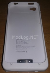
Broken it open to expose the internal circuitry and battery.
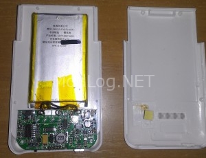
Solder a micro USB connector onto the battery leads.
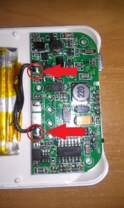
De-soldered the iPhone connector and cut a space to push the Micro USB lead through and reassembled.
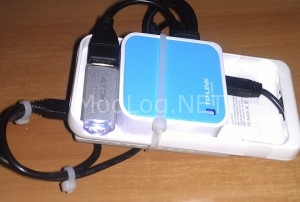
Checked the voltage on the leads before adding the external Micro USB make sure it’s still good to use, then checked it running with the external charging cable – All good. The blue lights indicate the current battery charge levels.
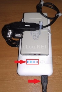
Features
- Full micro USB pass through (voltage and data) – allows charging and data through laptop/PC – Good for other projects, but the WR703N only excepts power in through the micro USB port.
- Batery charge indicator.
- Overcharge/surge protection through the circuitry near the battery.
- 1900mAh battery @ 4.2v, which I may replace with a few AA batteries later for extra running time.
- On/Off switch – allow charging or straight through power – Again, it wont be used in this project because the 5v supplied to the WR703N comes directly off the battery leads
Cheers
Good job, but how about the current? how many current is that? is the 1200mA current enough for wr702n? pls i need your answer, thx
Hi Amar, if its just the main PCB and no USB devices, Im guessing 1.2amps would be enough, the USB devices are what suck the most power and how much you need depends on what your using with it.
Cheers